| Previous | Main | Up | Next |
This is an introduction to the Texas Instruments LaunchPad MSP430 embedded development board, and to the IAR Workbench Integrated Development Environment (IDE).
To complete this workshop you should have a LaunchPad development board. You'll also require a Windows XP, Vista, or 7 computer to install and use the IAR Workbench IDE. This has been confirmed to work from within a VMware virtual machine on Macs. The computer must have an available USB port.
The LaunchPad kit includes:
The MSP430 family has been around long enough that development tools are available for Windows, Linux and Mac. This workshop only uses Windows and the IAR Embedded Workbench. There are additional tools, including one based on Eclipse, and another which is open source and based on GCC. More options exist for Windows, and the tools are stable. Mac is experimental.
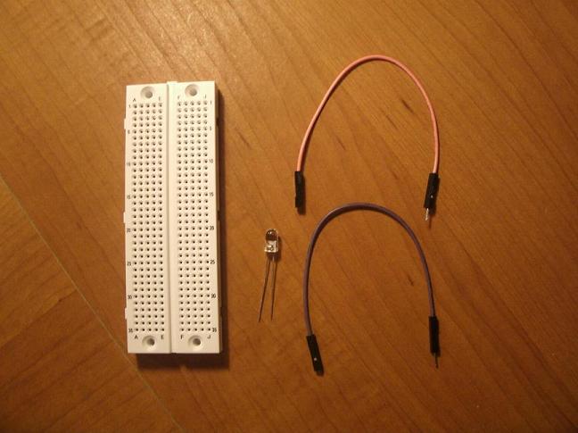
For the exercises you'll need two male-to-female jumpers, a solderless breadboard, and an LED.
|
|
| 2012-06-02 Mouser LaunchPad Lecture 50 pack Quote.pdf |
The parts we ordered for the workshop are in this quote. This provides enough for 50 attendees. Note that the jumpers come in a 10-pack, and each attendee requires two jumpers, so only 10 of these are needed. The rest are one-each.
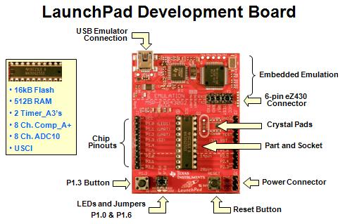
We'll take a quick look at your new board.
The primary chip is the MSP430. It does come out so you can swap the 2553 with the 2452 or other chips. Any MSP430 chip in the x2 family works. Current chips are either F2xxx or G2xxx.
The development board is in two parts. The emulator gives you a USB computer interface. You can disable and disconnect this by pulling the pins in J3. If you come up with a project that uses the LaunchPad then you'll probably want to provide power through the J6 pins and remove all of the J3 pins.
Our version of the LaunchPad comes with a G2553 chip. The key features are listed in the small box. The board works with a lot of chips - pretty much anything in the G2xxx or F2xxx family. The G2xxx chips are the low cost series. The F2xxx chips are more expensive (typically) but come with additional features. For example the F2003 and F2013 include a sigma delta 16-bit ADC which is not offered in the G2xxx series.
You can buy the chips in small quantities from Mouser, DigiKey, or others. Expect to pay between $1.10 (for the F2001 or G2001) and $2.50 (for the G2553 or F2013). Look for the PDIP packaging.
Texas Instruments has a lot of material for you. The following slide is from a very thorough workshop which will introduce the board, the MSP430, walk through many of the features, and show you how to use the Eclipse based development environment, Code Composer Studio.
|
| http://processors.wiki.ti.com/index.php/Getting_Started_with_the_MSP430_LaunchPad_Workshop |
My workshop is much more basic than the Texas Instruments workshop. But once you've completed this basic workshop you should start learning more from other resources, such as the Texas Instruments workshop. Follow the link above to find all the slides, documents, code samples, and links to videos of their presentation.
Look over the board and find the J1 through J6 headers.
Discuss static electricity and discharge.
All pins (except J4) are 1/10 inch spacing. This is common and is what your breadboard uses as well.
J1 and J2 simply bring out all the pins to male headers. Your kit included female headers so you can desolder the male and replace the default headers. We won't need that for this lab.
J3 connects the two parts of the board. We'll leave this connected.
J4 is an empty header to connect eZ430 target boards. You can buy F2xxx target boards in really small sizes. There are also RF target boards.
J5 disconnects the red and green LEDs. We'll use one of these shortly.
J6 lets you power the board from a battery. You can also use these pins to provide power for something else, such as the breadboard we'll use in the second exercise.
When the board is powered by the USB port it operates at 3.547 volts. The processor will operate from 1.8V to 3.6V.
See slau318 for more details on the board. This is the user's guide for the board.
Note that as of August 2012 there are other LaunchPad boards. The list of boards includes the original MSP430 board, a newer C2000 board, and soon an ARM board based on the Stellaris processor.
On to the first exercise - learning about the code already programmed into the chip.
| Previous | Main | Up | Next |